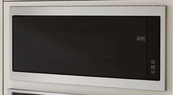
Your Whirlpool microwave display suddenly went dark, leaving you staring at a blank screen. Maybe it shows garbled symbols instead of the time, or perhaps it won’t respond at all. Either way, you can’t set cooking times, monitor progress, or access any functions. The unit might beep when you press buttons, or it might remain completely unresponsive.
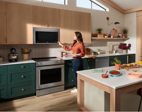
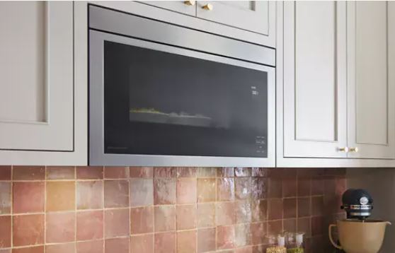
These display problems affect all Whirlpool models, from basic countertop units to premium over-the-range installations. However, most display failures are actually fixable without replacing the entire microwave.
Common causes of a Whirlpool microwave display not working include blown control board fuses (34% of cases), failed LED or LCD modules (28%), and loose ribbon cables (22%). Power supply issues account for 11% of failures, while surge damage causes about 5%.
Quick Diagnostic for a Whirlpool Microwave Display Not Working
| Display Symptom | Power Indicator | Button Response | Most Likely Cause | Typical Solution Cost |
|---|---|---|---|---|
| Completely black/dark | No lights anywhere | No beeps or response | Blown display fuse or dead control board | $5-$280 |
| Dim/faint display | Normal operation | Buttons work normally | Failed display backlight | $60-$120 |
| Partial segments missing | Display partially lit | Normal operation | Display module segment failure | $65-$130 |
| Garbled/scrambled text | Display illuminated | May work erratically | Loose ribbon cable or moisture damage | $0-$95 |
| Flashing or flickering | Intermittent illumination | Works intermittently | Loose power connection or failing capacitor | $0-$85 |
| No display after power outage | Interior light works | Buttons may respond | Tripped control board protection circuit | $0-$15 |
Understanding Whirlpool Microwave Display Technology
Modern Whirlpool microwaves use two primary display technologies, and knowing which type you have makes diagnosis much easier. The display technology affects both the symptoms you’ll see and the repair approach required.
LED displays consist of individual seven-segment numerical displays, with each digit containing seven LED elements. These elements form numbers and some basic letters through different lighting combinations. You’ll typically find LED displays in budget and mid-range models manufactured before 2020. They produce bright, high-contrast numbers that remain visible from wide angles, making them reliable.
LCD displays use backlit liquid crystal matrices to show more complex information beyond basic numbers. These screens can display detailed cooking information, settings menus, full text, and graphical indicators. Premium models and newer units from 2020 onward typically feature LCD technology. The displays offer more functionality but can be slightly more expensive to replace.
The display module connects to the control board through ribbon cables or dedicated wire harnesses. These connections carry both power and data signals between components, enabling the display to function properly.
Meanwhile, the control board generates all display signals and manages power delivery to the module. Every display problem ultimately traces back to one of three areas: the board itself, the connections between components, or the display module.
Why Is My Whirlpool Microwave Display Not Working?
Display failures manifest through various symptom patterns, and each pattern points toward specific component problems. Understanding these patterns helps you diagnose the issue quickly and apply the right solution. Let’s explore the five most common causes and their corresponding fixes.
1. Blown Display Fuse on Control Board
Many Whirlpool control boards include dedicated fuses that protect sensitive display circuits from damage. These small glass or ceramic fuses are designed to blow instantly during power surges. The display fuse typically rates between 1-3 amps at 125-250 volts, providing crucial protection.
When power surges occur from lightning strikes or utility switching, they create brief current spikes. These spikes exceed the fuse rating and cause immediate failure, which actually protects more expensive components. A blown display fuse cuts all power to the display module completely. However, the microwave might still function otherwise, with the interior light working and fans running.
Some models use resettable fuses called polyswitch devices instead of traditional fuses. These components reset themselves after cooling down, but their activation signals an underlying overcurrent problem. You’ll need to identify and fix that problem to prevent repeated failures.
How to diagnose a blown display fuse:
First, verify that your microwave receives power by checking if interior lights illuminate properly. This confirms that you’re dealing with a display-specific issue rather than a total power failure. Next, access the control board by carefully removing the outer cabinet panels. The display fuse mounts directly on the circuit board, making it relatively easy to locate.
Look for small cylindrical glass components with metal caps on each end. Alternatively, you might find small surface-mount ceramic fuses on newer models. Test the fuse continuity using a multimeter set (View on Amazon) to ohms mode. A good fuse shows zero resistance, while a blown fuse displays infinite resistance. Visually examine the fuse as well, since blown glass fuses often show visible damage.
How to replace a blown display fuse:
Remove the blown fuse from its mounting clips, or desolder it if it’s a surface-mount type. Through-hole fuses simply pull out with gentle pressure from small pliers or tweezers. Install an identical replacement that matches both voltage and amperage ratings exactly. Never use a higher-rated fuse, as that eliminates the protective function entirely.
Here’s the critical part: investigate why the fuse blew before reassembling everything. Blown fuses don’t fail randomly; they indicate real electrical problems in the circuit. Simply replacing the fuse without finding the root cause will lead to repeated failures. Check for damaged components, loose connections, or evidence of moisture near the display circuits.
| Fuse Type | Physical Appearance | Replacement Difficulty | Cost Range |
|---|---|---|---|
| Through-hole glass | Cylindrical, metal caps, visible wire | Very easy (pull and replace) | $1-$3 |
| Surface-mount ceramic | Small rectangular component | Moderate (requires desoldering) | $2-$5 |
| Blade-style mini fuse | Plastic body, blade terminals | Easy (pull from socket) | $3-$8 |
| Polyswitch resettable | Round disc or rectangular block | Easy to moderate | $5-$12 |

2. Failed Display Module Electronics
The display module houses several critical components, including LEDs, LCDs, driver electronics, and power management circuits. When any component fails within the sealed module, you’ll experience various display problems. The failure patterns differ significantly between LED and LCD technologies, which helps narrow diagnosis.
LED display failures typically show specific, recognizable patterns over time. Individual segments stop illuminating, creating incomplete numbers that become progressively harder to read. Multiple segment failures across different digits make the display completely unreadable. These failures usually indicate that individual LED elements have burned out from age.
LCD displays fail in distinctly different ways than their LED counterparts. The entire screen might go blank suddenly, or it could develop persistent dark spots. You might also see horizontal or vertical lines that remain visible constantly. Backlight failures create dim or nearly invisible displays, even though the panel itself functions.
Driver electronics serve as translators, converting control board signals into the actual display patterns you see. When these drivers fail, you’ll notice garbled displays showing wrong information or random symbols. Complete display shutdown can also result from driver circuit failures within the module. Meanwhile, power management circuits regulate voltage for sensitive components and commonly fail from surge damage.
How to test display module integrity:
Start by verifying that the display receives proper power from the control board. Use a multimeter to measure voltage at the display connector points. Check these voltage readings against your service documentation specifications, since most displays require 5-12V DC. The exact voltage depends on your specific technology and model number.
If proper voltage exists but the display remains dark, the module has failed internally. For LED displays, you can sometimes test individual segment LEDs if they’re accessible. Apply low voltage (2-3V) directly to suspected failed segments using a DC power supply. However, LCD displays rarely allow component-level testing because of their sealed construction entirely.
How to replace a failed display module:
Order the exact replacement display that matches your specific model number precisely. Generic displays never work correctly because pinouts and electronics differ significantly between models. Even displays that look identical physically won’t function if they’re designed for different units.
Disconnect the display ribbon cable or wire harness from the control board carefully. Release any connector locks before pulling cables to prevent terminal damage from excessive force. Remove the display mounting hardware next, which typically consists of screws or plastic clips. These fasteners secure the display to front panels or control assemblies firmly.
Install the new display in the exact same orientation as the original unit. Some displays only fit one way due to keyed connectors, while others physically fit incorrectly. Installing a display backwards or rotated can cause immediate, irreversible damage to both components.
Reconnect all power and data cables, ensuring they insert fully and lock properly. Partial connections frequently cause intermittent operation or completely non-functional displays.
Test everything thoroughly before final reassembly to avoid having to disassemble again later. Verify that all display segments illuminate correctly and information appears as expected. Run through several cooking cycles to ensure stable operation before securing all panels permanently.
Display module costs vary based on technology and complexity throughout the Whirlpool lineup. LED displays typically run between $60-$90 for most models. LCD displays cost slightly more, ranging from $80-$150 depending on screen size and advanced features.
3. Loose or Damaged Ribbon Cable Connections
Ribbon cables carry crucial data signals from control boards to display modules constantly. These flat, multi-conductor cables experience connection problems from continuous vibration and thermal cycling over time. The cables connect through pressure contacts at both ends, where connector spring tension holds conductors firmly.
Unfortunately, spring tension naturally weakens over years of thermal expansion and contraction cycles. Weakened springs create intermittent connections that cause frustrating display flickering or complete failure.
Additionally, oxidation forms gradually on cable and terminal contacts, increasing electrical resistance significantly. This corrosion prevents reliable signal transmission and causes various display malfunctions.
Cable flex points represent another common failure area that develops during normal use. Repeated flexing during door operation creates micro-fractures in the conductors over time. These tiny breaks produce intermittent conductivity, appearing as random display failures that seem impossible to predict.
How to diagnose ribbon cable problems:
Access the ribbon cable connections at both the control board and display module ends. Gently wiggle the cables while carefully observing the display response in real time. Flickering or brief illumination during movement strongly confirms connection problems rather than component failures.
Remove and thoroughly inspect cables for any signs of physical damage or wear. Look for tears, creases, burn marks, or discoloration that might indicate problems. Examine connector terminals closely for corrosion or damage as well during this inspection.
Clean the terminals using electronics contact cleaner (View on Amazon) if you notice any oxidation buildup. Finally, check connector locking mechanisms carefully, since broken retention clips prevent proper cable seating.
How to repair ribbon cable connection issues:
Clean all contact surfaces thoroughly with electronics contact cleaner to improve conductivity substantially. This simple step removes oxidation and contamination that interferes with signal transmission. Reseat the cables firmly to ensure complete insertion into their connectors properly. Listen for audible clicks or feel for positive engagement that indicates proper connection.
Replace damaged retention clips if you find any broken during inspection of the connectors. Some connectors use replaceable clips that snap in easily, while others require complete connector replacement. For cables showing physical damage like tears or severe creasing, replacement becomes necessary immediately. Ribbon cables typically cost between $12-$30, depending on length and conductor count.
Secure cables away from moving parts and heat sources during reassembly of the unit. Proper routing prevents future damage from mechanical stress or prolonged thermal exposure. Use cable ties or clips to maintain proper positioning throughout the microwave’s normal operation.
4. Control Board Power Supply Failures
Control boards contain sophisticated power supply circuits that convert standard 120V AC to lower DC voltages. These lower voltages power the display and logic circuits safely and efficiently. When power supply sections fail, displays stop functioning even though the microwave receives power.
Transformer sections step down the incoming voltage to appropriate levels for sensitive electronics. Failed transformers either output incorrect voltages or produce no voltage at all from their secondaries. Rectifier circuits then convert AC power to DC power through diode arrays. When diodes fail in these rectifiers, voltage output drops significantly and prevents proper display operation.
Filter capacitors play an important role by smoothing DC power and eliminating voltage ripple. Failed capacitors allow excessive voltage fluctuation, causing displays to flicker erratically or fail altogether. Voltage regulators maintain precise output voltages regardless of input variations or load changes. When regulators fail, they output wrong voltages that either damage displays or simply prevent operation.
How to test control board power supplies:
Measure DC voltages at the display connector terminals using a quality multimeter. Compare your readings against service documentation specifications for your specific model carefully. If voltages measure significantly low (more than 10% below specification), the power supply circuits have failed.
Check for AC ripple on DC voltage lines using an oscilloscope if available. Excessive ripple strongly indicates filter capacitor problems that need immediate attention. Measure current draw during display operation as well, since excessive current suggests short circuits. Finally, inspect power supply components visually for obvious damage like swollen capacitors or burned components.
How to repair control board power supplies:
Component-level repair requires advanced electronics skills and specialized equipment like soldering stations. Replacing individual capacitors, diodes, or regulators saves money but risks causing additional damage. Most homeowners should replace entire control boards when power supply sections fail completely. This approach ensures reliable repairs without requiring specialized expertise or diagnostic equipment.
Control boards typically cost between $180-$320 for genuine Whirlpool parts from authorized dealers. Aftermarket boards run cheaper at $120-$220 but sometimes have compatibility or longevity issues. Professional board-level repair services also exist as an alternative option for consideration. These specialized companies repair specific failed components for $80-$150, providing a middle ground solution.
5. Environmental and Power-Related Issues
External conditions sometimes cause display problems without actual component failures occurring. These environmental factors affect reliability and can mimic hardware problems closely. Understanding these influences helps you rule out component replacement when simple adjustments solve the issue.
High humidity creates condensation inside control panels, especially in coastal or basement installations. Moisture causes temporary shorts that create erratic display behavior and random malfunctions. Extreme temperatures also affect component performance beyond normal design specifications. Very cold or hot installations stress components and accelerate aging significantly.
Electrical noise from nearby appliances interferes with display signals in some installations. Motors, fluorescent lights, or other microwaves create electromagnetic interference that disrupts communication. This interference can cause garbled displays or intermittent operation without any hardware damage.
How to address environmental display problems:
Install dehumidifiers in high-humidity locations to maintain lower humidity levels consistently. This prevents condensation-related failures and protects electronics from moisture damage long-term. Ensure adequate ventilation around the microwave by maintaining clearances recommended in your manual. Good airflow maintains component temperatures within safe ranges and extends lifespan significantly.
Relocate or shield noise sources near the microwave if you suspect interference problems. Distance from electromagnetic interference improves display reliability and reduces random glitches. Use line filters on microwave power to remove electrical noise from incoming power. These devices cost $15-$40 and eliminate high-frequency noise that affects sensitive electronics.
Common Whirlpool Microwave Display Failure Patterns
Understanding typical Whirlpool microwave problems speeds up diagnosis considerably and helps you identify the root cause. These recurring issues affect specific model series and manufacturing periods. Recognizing these patterns saves time and prevents unnecessary component replacement when simpler solutions exist.
Flickering or Intermittent Display Issues
Displays that work inconsistently point to loose connections or marginal component failures. These intermittent problems frustrate troubleshooting through their unpredictability and seemingly random nature. Temperature-related failures appear under specific conditions that help identify the underlying cause.
Cold starts work fine but displays fail after warmup in temperature-sensitive failures. This pattern suggests thermal expansion affecting marginal connections or cold solder joints. Vibration-sensitive failures respond to physical disturbances like door slams or nearby activities. Displays work normally until mechanical vibrations disturb weak connections or failing components.
How to address intermittent display problems:
Test displays through temperature cycles using a hair dryer to gently warm components. Monitor the control board area while applying gentle heat to identify temperature-sensitive failures. Apply gentle pressure to suspected connection points with a plastic tool or finger. Displays responding to pressure confirm loose contact problems rather than failed components.
Monitor correlation between display failures and environmental factors like temperature and humidity. Track these variables along with vibration events, noting patterns that emerge over time. Reflow solder joints if you’re comfortable with soldering techniques and have proper equipment. Cold solder joints create intermittent connections that reheating with fresh solder resolves permanently.
Replace components showing temperature sensitivity after identifying them through thermal cycling tests. Capacitors and solder joints commonly develop temperature-dependent failures that require replacement.
Partial Display Segment Failures
LED displays losing individual segments create incomplete numbers that become progressively harder to read. These failures usually indicate LED element burnout rather than connection problems or driver issues. Seven-segment displays use seven individual LEDs forming each digit through various combinations.
Single LED failures create recognizable patterns like missing tops, sides, or middle segments. Driver IC failures affect multiple segments across different digits in identical patterns. These systematic patterns distinguish driver problems from individual LED burnout clearly.
How to identify segment failure causes:
Document which segments don’t light up by drawing display layouts and marking failed elements. Look for patterns affecting multiple digits identically, which suggests driver circuit problems specifically. Test individual LEDs if accessible by applying 2-3V DC to suspected failed segments.
For LCD displays, segment failures indicate panel damage that requires complete module replacement. Individual segment repair is impossible with LCD technology due to the sealed panel construction.
Display Shows Wrong Information or Symbols
Garbled displays showing incorrect numbers, random symbols, or scrambled text indicate communication problems. These issues stem from signal corruption between control boards and displays. Corrupted data signals create random display patterns that change unpredictably or remain constant.
Loose connections allow electrical noise to interfere with signal integrity and corrupt data. Software glitches occasionally cause display errors when firmware sends wrong information. Control board firmware bugs might send incorrect data despite proper hardware function.
How to fix garbled display problems:
Reseat all ribbon cables and wire harnesses to ensure complete insertion and proper locking. This prevents signal corruption from poor connections and oxidation. Clean connector contacts thoroughly to remove oxidation that increases resistance and degrades signals. Corrosion causes gradual signal degradation that manifests as garbled displays.
Shield ribbon cables if possible by routing them away from high-voltage components. Distance from motors and power circuits reduces electromagnetic interference significantly. Perform control board resets by power cycling for 10-15 minutes to clear temporary glitches. This simple step resolves software-related display errors without component replacement.
Update control board firmware if available for your specific model. Some models support firmware updates addressing known display communication bugs and improving reliability.
Whirlpool Microwave Display Not Working After Power Outage
Power outages create unique display failure scenarios that differ from gradual component aging. The sudden power loss and restoration surge stress display circuits differently than normal operation. Understanding these specific failure modes helps you diagnose and repair outage-related problems efficiently.
Surge Damage from Power Restoration
When utility power comes back after outages, brief voltage spikes often exceed normal levels. These restoration surges damage sensitive display electronics that lack adequate surge protection. The surge occurs as transformers energize and distribution systems stabilize after the outage. This transient might reach 150-180V briefly instead of normal 120V AC.
Display circuits lack surge protection in many models as a cost-saving measure. This leaves displays vulnerable to power restoration damage during every outage. Fuses blow to protect other components from excessive current during these surges. Display fuses sacrifice themselves to prevent more expensive control board damage.
How to assess surge damage after power outages:
Check the display fuse first, as this represents the most likely failure point. This simple check resolves most post-outage display problems quickly and inexpensively. Test all functions beyond the display to isolate the problem to display circuits. If other features work normally but only the display fails, surge damage is isolated.
Inspect the control board for visible damage like burned components or discolored areas. Severe surge damage leaves obvious visual evidence on circuit boards. Measure display power supply voltages using your multimeter to determine component damage. Correct voltages suggest display module damage, while wrong voltages indicate control board failures.
How to repair surge-damaged displays:
Replace blown display fuses first, as this simple fix resolves 60% of post-outage failures. The repair costs under $10 and takes just minutes to complete. Install surge protectors to prevent future damage from similar power events. Quality surge suppressors cost $25-$60 and protect against voltage spikes effectively.
Replace damaged display modules when fuses test good but displays don’t work at all. Surge-damaged displays rarely recover without complete module replacement. Consider control board replacement when power supplies fail and output wrong voltages. Surge damage to power circuits indicates significant component stress and potential future failures.
Control Board Reset Procedures After Outages
Some display failures after power outages result from control board protection circuits activating. These circuits require manual reset procedures that restore normal operation. Protection circuits monitor power quality and cut power during abnormal conditions automatically.
These protection systems sometimes fail to reset automatically after outages resolve. The control board enters protected mode to maintain safety and prevent damage. Manual reset procedures restore normal operation without component replacement in many cases.
How to perform control board resets:
Unplug the microwave completely by removing power at the outlet, not just circuit breakers. Wait 15 full minutes to ensure complete capacitor discharge and protection circuit reset. This extended duration is necessary for thorough power discharge from all components.
While unplugged, press and hold the Start button for 30 seconds continuously. This drains residual charge from circuits and resets protection mechanisms completely. Release the start button and wait another 2 minutes before reconnecting power. This additional waiting time ensures complete reset of all protection circuits.
Plug the microwave back in and check if the display illuminates properly. The display should light up showing the clock or initial setup prompts. If the display remains dark, attempt diagnostic mode entry using your manual. Some models require specific button combinations to force display activation after resets.
Consult service documentation for model-specific reset procedures if basic resets fail. Advanced resets might exist beyond basic power cycling for certain model series.
| Reset Method | Success Rate | Required Time | Risk Level | When to Use |
|---|---|---|---|---|
| Basic power cycle (5 min) | 40% | 5-10 minutes | None | First attempt for any display issue |
| Extended power cycle (15 min) | 65% | 15-20 minutes | None | When basic cycling fails |
| Start button discharge | 55% | 5 minutes | None | Power outage related failures |
| Diagnostic mode reset | 45% | 10-15 minutes | Low | Software glitch suspected |
| Control board button combination | 50% | 5 minutes | Low | Model-specific documented procedures |
GFCI and Circuit Breaker Considerations
Power outages sometimes trip ground fault circuit interrupters (GFCI) or circuit breakers protecting the circuit. These safety devices protect against electrical faults and overcurrent conditions. GFCI outlets detect ground faults and cut power instantly to prevent electrocution hazards.
These outlets don’t always reset automatically after outages and require manual intervention. Circuit breakers trip during power restoration surges when current spikes exceed their ratings. The breaker protects wiring from overcurrent during the voltage spike that occurs.
How to check and reset protective devices:
Locate the outlet or circuit breaker supplying your microwave in your electrical system. GFCI outlets have Test and Reset buttons visible on the outlet face. Press the Reset button on GFCI outlets firmly and listen for a click. The audible click indicates successful reset, and the button should stay depressed afterward.
Check your electrical panel for tripped breakers that appear in middle positions. Tripped breakers sit between On and Off positions rather than fully in either. Reset circuit breakers by pushing them fully to Off first, then back to On. This complete cycling ensures proper reset of the internal mechanism.
Test the outlet with another appliance after resetting to verify power delivery. Confirm proper voltage and outlet function before suspecting microwave-specific problems.
Advanced Whirlpool Microwave Display Troubleshooting Techniques
When basic diagnostics don’t identify the problem, advanced testing reveals obscure failures. These techniques require multimeter skills and electronic understanding but provide definitive answers. Signal tracing and component-level testing identify exactly where failures occur.
Signal Tracing from Control Board to Display
Systematically testing signal paths identifies exactly where failures occur in the circuit. This technique isolates problems to specific components and prevents replacing wrong parts. Obtain circuit diagrams for your model if possible from service manuals. Schematics show signal paths and voltage levels throughout the entire system.
Measure voltages at the control board display connector with power applied carefully. Document all readings for comparison with specifications and later reference. Measure voltages at the display module connector next and compare against control board measurements. Voltage drops between points indicate cable problems, while identical voltages confirm cable integrity.
Use an oscilloscope to observe data signals if you have access to one. Square wave patterns indicate proper digital communication between components. Signal tracing definitively identifies whether control boards, cables, or displays failed completely.
Component-Level Control Board Diagnosis
Skilled technicians can test individual control board components to identify specific failures. This advanced diagnosis identifies failed parts and enables targeted repairs. Check display driver ICs if accessible by measuring their output signals. These integrated circuits fail from surge damage or excessive heat exposure.
Test voltage regulator outputs with a multimeter to verify proper regulation. Failed regulators output wrong voltages and prevent display operation despite functioning upstream supplies. Measure capacitor values using a dedicated capacitance meter or ESR tester. Failed capacitors test significantly below rated values or show high equivalent series resistance.
Inspect solder joints under magnification looking for cracks or dull appearance. Cold solder joints appear dull and cracked, requiring reflow for reliable electrical connection.
Preventing Future Whirlpool Microwave Display Failures
Proactive measures significantly reduce display problem frequency and extend component lifespan. These practices address root causes before failures develop into expensive repairs. Install quality surge protectors rated for appliance use to protect from power spikes. Protect your microwave from surges that cause most catastrophic display failures permanently.
Maintain a stable power supply by addressing flickering lights or voltage fluctuations. Contact an electrician to resolve electrical service issues that stress display components. Poor power quality accelerates component aging and causes premature failures throughout the unit.
Keep control panels dry by wiping spills immediately to prevent moisture infiltration. Liquid damage causes immediate failures or delayed problems that appear weeks later. Avoid extreme temperature exposure by not installing microwaves near heat sources. Don’t place units in unheated spaces where temperature extremes accelerate component aging.
Unplug during extended absences like vacations to protect against surge damage. Disconnect your microwave when away to prevent damage from storms or power events. Clean vents regularly to prevent overheating that stresses display and control board components. Monthly cleaning prevents heat-related failures and extends overall appliance life significantly.
Test displays monthly by briefly checking all segments and functions during normal use. Early detection of fading or missing segments enables proactive replacement before complete failure.
Cost Analysis: Repair vs. Replacement
Display repair costs vary significantly depending on root causes and required parts. These economic factors guide repair-or-replace decisions for aging microwaves. Compare repair costs against replacement value considering your microwave’s age carefully.
| Problem | DIY Repair Cost | Professional Cost | Success Rate | Microwave Age Factor |
|---|---|---|---|---|
| Blown fuse | $1-$15 | $100-$150 | 95% | Repair regardless of age |
| Loose cable | $0 | $80-$130 | 90% | Repair regardless of age |
| Display module | $60-$150 | $180-$280 | 85% | Repair if under 5 years old |
| Control board | $180-$320 | $350-$520 | 90% | Consider replacement if over 7 years |
| Multiple components | $200-$400 | $400-$600 | 75% | Likely replacement makes sense |
Units over 8 years old with expensive repairs warrant serious replacement considerations (View on Amazon). Energy efficiency improvements in newer models offset replacement costs partially over time. Modern microwaves use 20-30% less energy than pre-2018 models.
Feature upgrades justify replacement for some users wanting modern conveniences. New sensor cooking, convection options, or smart connectivity might outweigh repair economics. Consider your usage patterns and desired features when making this decision.
When to Seek Professional Service
Some Whirlpool microwave display problems exceed safe DIY capabilities and require professional expertise. These scenarios warrant professional technician involvement for safety and reliability. Lack of proper tools prevents accurate diagnosis for those without multimeters.
Multimeters and basic electronics knowledge are minimum requirements for display repairs safely. Discomfort working with line voltage presents legitimate safety concerns that shouldn’t be ignored. Control board work involves 120V AC, creating real electrocution risks for inexperienced individuals.
Multiple failed repair attempts indicate complex problems beyond basic troubleshooting capabilities. Professional diagnostic equipment identifies obscure failures that basic testing can’t reveal. Warranty coverage significantly affects decisions about DIY versus professional repairs.
Active warranties typically cover display repairs, but DIY attempts void remaining manufacturer protection. Time constraints matter practically when you need your microwave functioning quickly. Professionals complete repairs within hours, while DIY approaches might extend over weeks.
Also Read:
- Why Your Whirlpool Microwave’s Start Button Isn’t Working ( & its Fix)
- Whirlpool Microwave Door Errors (Troubleshooting Guide)
- Common Whirlpool Over-the-Range Microwave Problems & Their Fixes
- How to Troubleshoot a Samsung Microwave Touchpad Not Working
Frequently Asked Questions
Why is my microwave display not working but everything else works?
The display fuse on the control board has blown or the display module itself has failed. Check if the interior light works and buttons beep to confirm power delivery. Access the control board and test the display fuse for continuity. Replace blown fuses for $1-$15 or the display module for $60-$150 typically.
How do I fix a microwave display that went blank after a power outage?
Power restoration surges blow display fuses that protect sensitive circuits from damage. Unplug the microwave for 15 minutes to perform a complete reset. If the display remains dark afterward, check and replace the display fuse. Install surge protectors to prevent future damage from similar power events.
Can a microwave work without a display?
Technically yes, but practically no for modern microwaves. If buttons respond with beeps, the microwave functions but you can’t set times. You lose all usability despite working heating components. Some models offer blind operation through repeated start button presses only. This proves extremely inconvenient and imprecise for actual cooking needs.
How much does it cost to replace a Whirlpool microwave display?
DIY display module replacement costs $60-$150 for LED displays or $80-$150 for LCD displays. Professional repair ranges from $180-$280 including labor and diagnostic fees. If the control board failed instead, costs rise to $180-$320 DIY. Professional control board replacement runs $350-$520 with labor. Simple fuse replacement costs under $15 DIY.
Why is my microwave display dim or fading?
The display backlight has failed (LCD displays) or LEDs are weakening (LED displays). This indicates approaching end-of-life for the display module electronics. Replace the display module before it fails completely and leaves you without function. Dim displays sometimes indicate failing power supply capacitors requiring control board attention soon.
How do I reset my Whirlpool microwave display?
Unplug the microwave for 15 full minutes to allow complete power discharge. Press and hold the start button for 30 seconds while unplugged. This drains residual charge from circuits completely. Reconnect power and the display should reset showing the clock or setup prompts. If this fails, check for blown fuses or damaged components.
Can I replace just part of the microwave display?
No, displays function as sealed modules that can’t be disassembled safely. Individual segment repair, LED replacement, or LCD panel fixes are impossible. The entire display module requires replacement when any part fails completely. Attempting to open display modules damages them beyond repair permanently. Always replace complete display assemblies for reliable repairs.
Master Your Whirlpool Microwave Display Repairs
Display problems look catastrophic at first but often resolve through simple repairs. Understanding display technology and common failure patterns enables effective troubleshooting. Most display issues cost under $150 to fix DIY with basic tools. You need moderate electronics knowledge and a multimeter for most repairs.
These repairs typically take 60-90 minutes including testing and reassembly time. Systematic diagnosis prevents wasting money on wrong parts unnecessarily. Testing fuses and connections before ordering expensive displays saves money significantly.
Document everything through photos of symptoms, test results, and repair procedures. These records prove valuable for future reference or when consulting professionals, especially when your Whirlpool microwave isn’t working well.